 |
||
|
||||||
|
|
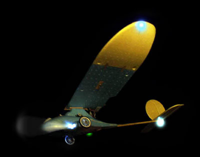
Flying R/C models at night has become popular in recent years. Not only is it a quite fun, but the nighttime visual aspects are simply stunning. This project will show you how to build a system that adds colored wingtip lights, anti-collision strobe, and remotely activated landing lights. It is ideal for scale model aircraft since functional lighting should help earn additional contest points. Nav-Lights connects to your receiver's throttle jack or any spare R/C channel. Your R/C equipment is not modified in any way. A clever "arming" sequence is used so that you can share your throttle stick with Nav-Lights' landing lights. The strobe light output can be set to a FAA standard single blink (85 per min) or a special double wink (60 per min). The blink pattern is programmed through your R/C transmitter. High brightness LED's are used throughout so current consumption is low (about 25mA per solid light, under 3mA per blinking light). As an added bonus, the system also counts radio glitches (signal interference hits), which is a handy diagnostic tool. It will display up to 99 hits via a small board mounted LED. Even if you do not care about the external lighting aspects, this feature is one that should interest anyone that is experiencing signal trouble at the flying field. Please be aware that flying model aircraft at nighttime requires additional safety measures. Your local club site may have special rules to follow, so please consult your safety officer before you take to the skies.
Nav-Lights' PIC is Simply BrilliantNav-Lights is based on a tiny 8-Pin chip. It is actually a MicroChip Technologies PIC12C508A MCU (microcontroller) running custom firmware which is provided at no-charge. The PIC decodes the R/C signal for landing light on/off control and blinks the strobe LED's. It also carefully checks the servo pulse for suspicious signals and will record any that are found as an R/C signal glitch. An onboard status LED blinks out the count. This LED is also used for diagnostics. Even though a microcontroller is used, cost is very low. You can build the Nav-Lights system, minus the LED's, for under $7. Total parts count is very low and the assembled board weighs under 10 grams. It can be as small as you care to make it (mine is about 1.25" square).
The digital inputs are level sensitive and are said to be logic high when the voltage is > 2.0VDC and logic low when they are less than 0.5V. Typical designs will use the VCC voltage (pin 1) for a logic highs and GND voltage (pin 8) for lows. Output voltages are easily defined. Logic high output voltage is equal to VCC and a logic low output is 0VDC. The output sink/source drive current is up to 20mA (plenty for our application). If you are ready, let's take a quick tour of the various signals on the PIC chip:
The PIC12C50x is not
a "Flash" part, so you will need a traditional PIC chip programmer to "burn"
the hex file's object code into the microcontroller. Be sure to select the
configuration fuses during chip burning as follows (these are optional settings
within your chip programmer's menus):
By the way, after you program the PIC it will fail the verify cycle. Do not be alarmed -- everything is OK. Just ignore the "failure." Whatever you do, do NOT program the chip twice! If you have trouble burning the PIC, then please check your programmer. Whatever the fault, it is not a CamMan hex file issue. The most common problem is that the user has forgotten to burn the PIC's four config fuses, as shown above. More programming information can be found starting here. The entire firmware is written in "C." You do not need to know anything about the C language to build your system. All you need is the object code to program the PIC, which is provided at no charge for personal use. This means that any hobbyist can use the firmware for free. But, anyone that desires to use it in a product for sale (or wishes to sell pre-programmed parts) must first obtain written permission. Sorry, but I will not provide the text based source code.
Construction: Circuit du Soleil
Perfboard layout is not critical except that the C1 cap should be close to the PIC and C2 (if used) should be connected directly to J1. Use a socket for the Nav-Light chip. If you will NOT be sharing the receiver channel with a servo then you can omit J2. Install all the parts except the LED1 thru LED5 lamps (we will work on that in a moment). The optional on/off switch allows you to turn off the lights, while retaining the glitch count feature. If you do not need the switch then just replace it with a jumper wire. The schematic shows a typical complement of LED's (two wingtip, two landing, and one tail strobe). However, you can add more lamps as you see fit. The Q1 and Q2 buffer transistors will handle up to 500mA, so a couple dozen LED's are possible. Each LED needs its own current limit resistor -- NEVER share a single resistor with two or more LED's (that is asking for trouble).
Using the "LED Roundup" information from the RC-CAM LED Calculator Page, I decided on the following LED's:
The LED's are connected to the board using long lengths of small gauge wire. I highly recommend using 30AWG Kynar (wrapping wire), such as Radio Shack part numbers 278-502 (white) and 278-503 (blue). These wires must be twisted along their entire lengths (at least two twists per inch) to prevent interference to your R/C system. Do not worry about the wire's small size -- it will carry enough current for any LED that you may use. Be careful how you run the wiring near your receiver's antenna. Some R/C installations have antennas that run down the length of the fuselage or inside the wings. This is same path that your LED wires might need to travel. The two will not get along (especially the strobe) unless you separate them by at least a couple of inches. My SoarStar's rear fuselage/tail boom is just a stick, so separation was less than a quarter inch. Early on I found that some occasional glitches would occur.
By the way, the LED colors that I used are not exactly "scale" since you will never see a blue light on a left wing tip. If you are a stickler for authenticity then please use FAA colors on your model. If you would like to know more, these web links offer generalized information on aviation lighting:
Set Up and Operation:Double check your work, especially the J1-J2 R/C connectors and U1 pins 1 and 8. Simple mistakes can destroy electronic parts, servos, and may generally ruin your day. I will assume that you will be sharing your throttle channel with Nav-Lights. Plug J1 into your receiver's throttle channel and connect the servo to J2. If your model is electric and you are using an ESC (electronic speed control) then be sure to disconnect the e-motor to prevent injury. Turn on the R/C transmitter and apply receiver power. You should see that the Status LED is off and that the Strobe light is winking/blinking at about 1Hz. If not, remove power immediately and check you work. Now let's test the landing lights. First you must "Arm" the system. Move the throttle stick to full low stick then give it full up stick (do not cheat -- use FULL deflection on both extremes). Nav-Lights is now armed. If you reduce throttle to below half-stick you should see the landing lights come on. They will remain on if you increase the throttle, but full up stick will turn them off. Practice a bit -- you will quickly see how it works. If the landing lights do not come on then you may have a wiring problem or an insufficient ATV mix setting in your R/C transmitter. First you should check your wiring. If it looks good then you will need to increase your up/down ATV mix settings (if available) so that they are at 100%. If you are using another channel besides throttle, be sure that its Dual Rates mix is disabled.
I should mention that once you arm the Nav-Lights system (full down stick then full up stick) the throttle will control the landing lights. Any stick position near half-throttle will turn them on and FULL up stick is required to turn them off. This works nicely with the way you will come in for a landing. But if you wish to fly around with the landing lights on then just avoid full throttle. I do this all the time on the Soarstar and there is no speed difference when I limit the throttle stick to just under full stick.
If you are using a
spare R/C channel (the gear channel works well) then the operation is nearly
the same. To perform the initial system arming just flick the channel's toggle
switch down-up-down. From then on you have switch controlled access to the
landing lights. If the switch operation is backwards then either use your
transmitter's channel reversing feature or install a jumper at JP2.
Name Your Poison - Wink or Blink?You have your choice between a standard FAA approved strobe blink or a special double wink cadence. These two patterns are ideal if you and a friend will be flying at night together -- just use different patterns so that you both can identify your model (things can get confusing in the dark). Enabling the strobe pattern is done from the R/C transmitter. Let's assume that you are using the throttle channel to control the Nav-Lights. Start with you R/C receiver turned off. If you want a double wink (my favorite) then set your throttle stick to low before turning on the receiver/PIC power. If you want a single blink then move your transmitter stick to full throttle and then turn on receiver/PIC power. Remember, the transmitter must be on, and the throttle stick in position, before you turn on the receiver/PIC power. The chosen strobe pattern will remain until receiver power is removed. Some electric models use self configuring motor speed controls (ESC) that require the throttle to remain low when the R/C receiver is first turned on. This will interfere with setting the single blink strobe. However, you can add a normally closed push switch in series with the PIC Pin 1 and a 4.7K resistor in series with PIC Pin 4. With these extra parts you can enable the double wink. Just turn on the transmitter, then the receiver, and wait a moment for the ESC to initialize. Move away from the prop and move the throttle stick to 3/4 or higher. Lastly, press and release the added switch to interrupt PIC power (this performs a power-up software "reboot"). The strobe mode will now be updated.
Diagnostics: Is there a Doctor in the House?The Status LED (LED1) is used for system diagnostics. It can tell you if the receiver's servo signal wire is disconnected, if the R/C signal is missing (e.g., transmitter off), and it counts the number of R/C interference glitches that occurred during flight. If the Status LED is off, with no flashing (and the strobe is blinking normally), then everything is fine. This is what you want to see as it indicates that the servo signal is present. If you experience short duration (harmless) R/C interference then the Status LED will flash intermittently, but there wont be a recognizable pattern. If the servo signal is missing the Status LED will be on solid. If during this time the Strobe LED is blinking at a very rapid rate (10Hz) then the problem is due to a disconnected servo signal wire. If the Status LED is on, but the Strobe is blinking at the normal rate, then your transmitter is probably turned off. Anytime there are several consecutive servo pulses that do not meet acceptable criteria, the Nav-Lights assumes a radio "hit" (interference glitch) has occurred. The hit count will be incremented and this will be used as the Status LED's blink pattern. Further hits will not be counted until reliable radio communications has been re-established. For a demonstration of the glitch counter feature just turn on your transmitter and model while they are safely on the bench. Then turn off your transmitter for a moment. You will notice that the Status LED is now on solid, which indicates that the R/C signal has been lost. Next, turn the transmitter back on and observe the Status LED for a few seconds. You will see it blink once, pause for a few seconds, then repeat. Extremely short duration radio interference is deliberately not counted as a "hit." Instead it will appear as a random flash on the Status LED while it occurs. Now flick the transmitter switch on and off several times in a row at very fast rate. End with the transmitter turned on. You just simulated an extended radio glitch. Rather than count this as several hits, this rapid fire string of bad signals is tallied as just one. Your Status LED should now blink twice, delay for a few seconds, then repeat. The hit count can be reset by cycling receiver power. Up to 99 hits can be recorded.
Design Documents:The technical details are available as file downloads. There is no charge for the information when used in a personal (hobby) project. Commercial users must obtain written approval before use. Please be aware that the information is copyright protected, so you are not authorized to republish it, distribute it, or sell it, in any form. If you wish to share it, please do so only by providing a link to the RC-CAM site. You are granted permission to post links to the web site's main page (http://www.rc-cam.com/). Please respect this simple request.
Additional ApplicationsBare Bones Glitch Counter: You do not need to build the full Nav-Lights board if all you want to use is the Glitch Counter feature. In this case just stuff J1, U1, C1, R8, and LED1. Five components are that is needed to record those intermittent radio hits. R/C Accessory On/Off control: The landing light control output can also be used as a general purpose remote on/off control. The Q2 transistor can drive a 5VDC low current relay (>100 ohm coil) or use the AQV212 opto-relay if your load is under 400mA. Lost Model Alarm: You can replace R8 and LED1(Status LED) with a loud piezo beeper. If your model is lost in the brush then just turn off your R/C transmitter and hunt down the loud beep. As a side benefit, your model will beep when you've been hit with a signal glitch while you fly your electric model (nitro models are too loud to hear the beep in flight). I suggest that you use a DigiKey 102-1124 5V piezo buzzer since it can be driven directly from the PIC (no buffer needed) if LED1 is removed.
The Small Print:
All information is provided as-is. I do not offer any warranty on its suitability. That means that if you build and use this device, you will do so at your own risk. If you find software bugs then please report them to me. I can only make corrections if I can replicate the bugs, so please give me enough details to allow me to witness the trouble.
FeedBack:If you have technical questions or comments about this project then please post it on the rc-cam project forum.
|
||||||||||||||||||||||||||||||||||||||||||||||||||||||||||||||||||||||||||||||||||||||||||||||||||||||||||||||||||||||||||||
 There
are eight pins on the Nav-Lights (PIC) chip. They exist as one of three kinds
of signals: Power, Digital Input, or Digital Output.
There
are eight pins on the Nav-Lights (PIC) chip. They exist as one of three kinds
of signals: Power, Digital Input, or Digital Output.
 The circuitry can be built using
nearly any technique you wish. Mine was built on phenolic perfboard and
point-to-point wired using 30 gauge insulated Kynar wire. This wire is normally
used for wirewrapping, but works fine with a soldering iron. I just
strip a bit of insulation off and solder it to the parts. I recommend a 40
watt or less soldering iron (700° tip).
The circuitry can be built using
nearly any technique you wish. Mine was built on phenolic perfboard and
point-to-point wired using 30 gauge insulated Kynar wire. This wire is normally
used for wirewrapping, but works fine with a soldering iron. I just
strip a bit of insulation off and solder it to the parts. I recommend a 40
watt or less soldering iron (700° tip).
 You
can also download the Printed Circuit Board (PCB) and etch your own board
(see drawing at right). The PCB is 1.3" x 1.0" and is a simple single sided
design suitable for home etching. There are two jumper wires on it. Cap C2
has been eliminated on the PCB layout (it is only used on perfboard
construction methods). Sorry, but I do not offer an etched PCB. I don't sell
a parts kit either.
You
can also download the Printed Circuit Board (PCB) and etch your own board
(see drawing at right). The PCB is 1.3" x 1.0" and is a simple single sided
design suitable for home etching. There are two jumper wires on it. Cap C2
has been eliminated on the PCB layout (it is only used on perfboard
construction methods). Sorry, but I do not offer an etched PCB. I don't sell
a parts kit either.
 Not
to worry -- In cases where servo glitching occurs at the strobe's blink interval,
a tiny ferrite ring core (toroid) should be installed on the LED cable that
is nearest the antenna. The core must be installed within one inch of the
Nav-Lights circuitry. At least five wraps (more is better) tightly threaded
around the toroid core is all that is needed. I used a toroid from my junk
box that was 0.31" OD x 0.15" ID x 0.14"H). The
tiny
Not
to worry -- In cases where servo glitching occurs at the strobe's blink interval,
a tiny ferrite ring core (toroid) should be installed on the LED cable that
is nearest the antenna. The core must be installed within one inch of the
Nav-Lights circuitry. At least five wraps (more is better) tightly threaded
around the toroid core is all that is needed. I used a toroid from my junk
box that was 0.31" OD x 0.15" ID x 0.14"H). The
tiny