 |
||
|
||||||
Author commentary: Although the RC-CAM2 system is no longer used, you will certainly learn a lot by reading the details to building it. Like many good things, its useful life has come to an end and it has been replaced by the latest project called RC-CAM3. But for historical benefit, the original RC-CAM2 project is listed below. Enjoy!
If you haven't read about my RC-CAM1 prototype then please click the link at the top of this page. Otherwise, lets get into the details on how you can build your own airborne video system for under $100. And as we have discussed, we will mount it on a radio controlled model helicopter.
The improved system is called RC-CAM2. It works better AND it costs less than my earlier attempt to get a wireless video system on my flying model. The only caveat is that there is some assembly (or disassembly as you will soon find out) required.
 The actual video camera, transmitter and receiver was purchased as
a ready-to-use wireless video system from
www.x10.com, a firm that sells
home automation devices. The wireless system is called XCam and it was purchased
for $100 in 1999.
The actual video camera, transmitter and receiver was purchased as
a ready-to-use wireless video system from
www.x10.com, a firm that sells
home automation devices. The wireless system is called XCam and it was purchased
for $100 in 1999.
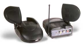
The photo on the right shows the tiny COLOR camera as well as the video sender transmitter and receiver set. The system was designed for indoor use and has an advertised range of one hundred feet. The color camera is low resolution and is about the same video quality as you get from a VHS tape recording.
I was surprised to discover that the XCam color camera system that I just purchased has already been replaced with a newer model. I have not hacked the newer camera so you will have to improvise a little, but the video senders are the same. The new camera has a built-in microphone, a nice feature that will help reduce some of the modifications that I had to perform.
The newest "XCam Anywhere" system can be seen at http://www.x10.com/products/x10_vk34a.htm. Remember, this is not the model that I used but I do not think that you will find any major obstacles in using it. And it currently sells for $88, not a bad price for a color camera, transmitter and receiver.
The unit transmits on 2.4 GHz and does NOT require a ham radio license to operate. This was an issue with my original RC-CAM1 which operated on the 434 MHz ATV ham band. The micro-sized color camera uses a CMOS imaging sensor that draws only 30 milliamps @ 9V, which helps maintain battery life. My original RC-CAM1's CCD B/W camera used four times that amount of current.
The downside is that the XCam camera has low resolution but is perfectly usable. Its auto iris is somewhat slow and can washout during quick dark-to-light transitions. And line-of-site range is only about 300 feet on a good day (a better receiver antenna would extend the range considerably). But these issues are not bad enough to hold up the project, especially when you consider the bargain price.
Ok, if you have not realized it yet, we have some problems to overcome. Let's see... we need very light weight airborne electronics and simple battery operation. Yikes, the XCam system is powered by household current and is big and heavy. Time to get creative!
The project involves tearing apart the XCam transmitter, reducing its weight, converting it to 4.8VDC battery operation, and packaging it in a light weight box. Sounds simple enough don't you think?
But let me impress upon you that you must check your XCam system to see if it works before you attempt my modifications. This is your chance to see if the XCam system works correctly and to your satisfaction. If not, return it now. Enough said?
Within two minutes I had the cover off the video transmitter. This plastic box enclosed unit came apart after removing four case screws. Inside was nothing scary -- a bunch of discrete components and a shielded sardine can type RF section.
Before I continue lets get one thing perfectly straight. By taking the product apart you have no moral or legal right to return the unit to the vendor. If you screw up you will be the proud owner of a silicon based paper weight. If this freaks you out then by all means put away the screwdriver before you dork the unit up!
If you are still with me then you have decided to forge ahead to reconfigure your transmitter to its new life in your model heli. If you have any doubts about your abilities to read schematics or solder then this is not the time to decide to learn a few tricks. Don't be a hero -- put the screwdriver down now!. Or as the little dog says, "drop the Chalupa."
I've warned you twice, so now I'll stop badgering you. So, on with the screwdriver.
 By the way, the transmitter
is marked VT30A on the bottom. Frankly it would be embarrassing if you took
apart the identical twin video receiver identified as the "VR30A."
By the way, the transmitter
is marked VT30A on the bottom. Frankly it would be embarrassing if you took
apart the identical twin video receiver identified as the "VR30A."
Oops... Now that you have the receiver back together let's take apart the correct unit, the VT30A transmitter. By the way, the back label can remain in place if you treat it like a hinge during disassembly.
Now you can look around inside the video transmitter. You should be able to quickly identify REG1, the LM7808 regulator and its heatsink and the J4 12VDC power entry jack. Resist all temptations to dork with the inductors and such.
I promised not to bother you again but if you do not know what these parts are then STOP, re-install the cover, and go about your everyday business. Ok, that's really the last time I will try to stop you.
Ok, enough with our initial transmitter geography. It's time to remove all the bulky plastic parts and leave just the circuit board. Here is the order I followed which you may find helpful:
The stock camera and video transmitter use a 12 VDC wall adapter. However, I had previously used my bench supply and found that the camera and transmitter could be made to work with as little as 8 VDC. However, the radio control system in my model helicopter is powered by a 4.8VDC battery pack. I had a round hole - square peg sort of situation.
But this situation is not a problem. I could have used a second battery pack but I wanted to save on airborne weight. The no-brainer custom power supply circuitry I devised will allow us to run the camera and video transmitter from the model heli's existing NiCd battery pack.
Just think, you will not need a separate battery pack. This will certainly simplify the installation at the expense of a little up-front work. This magic is obtained from a cheap DC-DC Power Converter Module that weighs less than 1/2 ounce.
The idea of using a DC-DC power module to get useful voltages is not a new one, but this is the first time it probably has found its way on a R/C Model Helicopter. In our case we need 9VDC @ 160mA so I scouted around a few catalogs to find a low cost solution. A good candidate was found in the Jameco Electronics catalog (http://www.jameco.com) as part number 123895 and it cost only $4.
The Jameco part comes in a 24 pin DIP package and requires no external parts to operate. Its original use was for networking cards but nothing will prevent us from putting this surplus part to a more important use.
| Because the RC-CAM current drain is about 400 milliamps @ 4.8V, your heli's NiCd batteries will discharge quickly. If you are using a Piezo gyro and have a 1400mAh or larger battery pack for your R/C radio then you should get several flights. If you have a mechanical gyro and/or a lower capacity airborne battery then plan on only a couple flights. If necessary, use a separate NiCd or NiMH battery pack for your RC-CAM transmitter. |
The parts lists sources are http://www.jameco.com and http://www.radioshack.com.
Of course you can use your local supplier if you know how to substitute the parts. But PLEASE don't email me asking for my opinion of your sub'd part. If in doubt please go to these sources. If you have a personal grudge with either of them or if mail order is not convenient then by all means use your favorite source.
Qty |
Description |
Reference |
Source |
PRICE |
1 |
470 ohm 1/4W Resistor | R1x |
Jameco 31165 |
$0.09 |
1 |
100K ohm 1/4W Resistor | R2x |
Jameco 29997 | $0.09 |
3 |
10K ohm 1/4W Resistor | R3x, R4x,R5x |
Jameco 29911 | $0.09 |
2 |
100uF 16V Electro Cap | C1x, C2x |
Jameco 158191 | $0.10 |
1 |
.1uF Mono Cap | C3x |
Jameco 25523 | $0.15 |
1 |
22uF 6V Tant Cap | C4x |
Jameco 33751 | $0.32 |
1 |
10uF 16V Tant Cap | C5x |
Jameco 94060 | $0.45 |
1 |
5V to 9V DC-DC Convertor | U1x |
Jameco 123895 DISCONTINUED PART |
$3.95 |
1 |
24 Pin DIP Socket | U1x Skt |
Jameco 39351 | $0.59 |
1 |
LM358 IC OP AMP | U2Ax |
Jameco 23966 | $0.29 |
1 |
8 Pin DIP Socket | U2x Skt |
Jameco 51625 | $0.29 |
1 |
Electret Microphone | MICx |
Radio Shack 270-092 | $2.99 |
1 |
PN2222A Transistor | Q1x |
Jameco 28628 | $0.11 |
We will build the three circuit elements in stages and test each one. The three circuits are (1) The DC-DC Power Supply, (2) the voltage regulator, and (3) the microphone preamp. All construction is "dead bug" style and should take less than two hours. We will also change the video camera's wire harness.
Here is what we will be building. Are you up to it?

(1) DC-DC Convertor Construction
The DC-DC supply IC is functional right out of the box, but we need to add some decoupling caps and the R/C servo style power connector. I recommend that you mount the convertor on a 24 PIN DIP machine pin socket and add the parts to the bottom per the schematic and photo below:
 |
 |
Use 24 AWG stranded wire on your harness and leave about 8" on the NiCd input and +9V output. I suggest using different wire colors to protect yourself. To plug the convertor into your R/C radio system you will need to obtain a compatible plug from your hobby store. If you have a dead servo in your junk pile then just cut off its harness at the servo end. Splice your R/C connector to the NiCd input of the convertor. Pay attention to the polarity or I suggest you look for some good fire insurance.
Before you do anything take your ohmmeter and verify that you do not have a short across the NiCd input leads. The resistance should be over 50K ohms. If not, fix your mistake now or prepare a bucket of water.
If you have a regulated bench supply then set it for +5VDC and if possible limit its current to about 400mA. Otherwise you will need to use your exisiting R/C airborne radio gear. In the latter case, plug the convertor into a spare servo channel or use a servo "Y" harness. I recommend that you use a Y harness directly on the radio control system's battery pack.
Hook a DVM across the +9VDC and Gnd output connections. Turn on the power -- if you don't see +9VDC (+/-1VDC) then turn off power NOW and fix your mistake. Smoke or burning odors are not a good sign either.
WARNING: You can't use the AC Wall Adapter on the XCam transmitter. Due to the modifications you will need to use a 4.8V NiCd battery or 5VDC bench supply. |
(2) Voltage Regulator Construction
Now let's assemble the voltage regulator. The design is a single transistor configured as capacitance multiplier and it helps isolates power glitches to our XCam transmitter board. The transistor imposed voltage drop will take our nominal 9V from the DC-DC supply and give us a healthy 8V output.
The four new components mount on the transmitter board in the holes that held the original REG1 (LM7808) IC regulator. As you may recall, the REG1 part was removed earlier. If you forgot to remove it then you are a little lost and you should click < HERE >.
When looking at the circuit board's REG1 pinout the pins are identified as 1-2-3. Install the parts as follows:
|
 |
 |
The photo and drawing shows the voltage regulator mods. Q1x, C1x, C2x, and R1x all mount in the holes near the old REG1 location. Be sure to study the board's artwork and the regulator schematic before adding your parts. Cap C2x was installed in some spare holes that were buried under the factory applied hot melt glue. Keep the leads short or engine vibration will cause you trouble later on. |
Check over your work and if it looks correct then solder the DC convertor's "+8V" and "Gnd" leads to the transmitter's J4 power entry jack (on the board's solder side). To save weight I removed the jack and soldered the wires to the holes. Observe polarity!
Once again apply power to the NiCd power input connector. You should see the transmitter's LED light up. Use your DVM and verify that C2x+ has 7.8VDC to 9.0VDC on it. Your meter's ground connection can use the shield metal of the RF can.
If you don't find the proper voltage then start troubleshooting. The circuit is simple, so any problems should be easy to fix. If things appear dead then you may want to check the board's On/Off switch.
(3) Microphone
Preamp

My XCam system did not include a microphone so I added a little electret mic and preamp circuit. You may not care about audio (but it adds another dimension to the flying experience) so just ignore this circuitry if you wish to omit the mic feature.
I built the preamp on the bottom of an 8 pin DIP machine pin socket. Keep the component leads short and follow the schematic.
 After mounting all the discrete
parts to the bottom of the socket, connect the preamp to the three mic leads
(Power, Signal, Gnd). Using about five inches of stranded wire, connect the
preamp to +8V and Gnd of the regulator circuit. Solder the output of the
preamp to the Left and Right Audio input jacks.
After mounting all the discrete
parts to the bottom of the socket, connect the preamp to the three mic leads
(Power, Signal, Gnd). Using about five inches of stranded wire, connect the
preamp to +8V and Gnd of the regulator circuit. Solder the output of the
preamp to the Left and Right Audio input jacks.
Cover the finished preamp circuit with heatshrink tubing or electrical tape.
(4) Color Camera Harness Mods
The wire harness on the color camera is much too long and makes for a clumsy installation. Fortunately we can rectify that issue in a jiffy.
Using some tape or a pen, mark the top of the lens and the camera case. Using a small screwdriver, carefully pry the camera case open at its seam. It should easily pop apart and inside you will see a splice connection. Just unsolder the splice joints and add a 6" piece of black and red 24 AWG stranded wire to the small pigtail wires. Just match the colors and use heatshrink for insulation.
While observing the indent tabs, press the case halves back together. Just follow the orientation marks that you made earlier. Make sure that your new wire harness exits out the cable notch.
Press the camera onto the transmitter's yellow video connector. Leaving a couple of inches for a service loop, solder the red and black leads to the J4 jack area. Observe polarity!
Temporarily solder a 5" piece of wire to the antenna coax's center conductor. This will get a permanent rigid antenna in a few moments.
(4) System Checkout
To check the camera and microphone you will need to install the XCam receiver on your TV or VCR and apply power to everything.
Verify that you have video and audio. If you run into trouble verify that the XCam transmitter and receiver are still set to the same channel (A-B-C-D) and the On/Off switch is "on." The mic should pick up your voice within several feet. If not, fix the preamp circuit.
Turn on your R/C transmitter. If you find video interference then change the XCam transmitter and receiver to a different A-B-C-D channel. My radio caused lots of snow on two of the A-B-C-D settings.
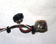
 Now we have a bunch of stuff
that looks like the photo on the right. It really needs to be protected in
a light weight box before mounting it in the model heli.
Now we have a bunch of stuff
that looks like the photo on the right. It really needs to be protected in
a light weight box before mounting it in the model heli.
If you were diligent during assembly the entire mess should weigh less than five ounces at this point. Now we will switch our efforts to building a protective box. It is important that it does not increase the weight too much.
I took the cardboard shipping box that the XCam came in and cut it up as follows:
Using a hot melt glue gun and some clever folds, I built an enclosure as shown. The top is hinged at the rear and there is a cutout for the rear LED. As shown in the photos, the camera is recessed into the box and the microphone hole is to the right of the camera area.
|
|
|

When the box was complete I spray painted it with fuel proof model airplane paint (don't skip this step or you will have fuel soaked cardboard after a few flights).
Total weight is under two ounces. I spent a couple hours building and painting it and cost was nearly ZERO.
The XCam circuit board mounts in the box with two plastic 6-32 screws and is held in place with two 1/2" long plastic standoffs acting as nuts. The top cover has two holes that allow me to use a couple more screws that thread through the top and into the standoffs. The clamshell design is efficient and works well.
As a final element to our project we need to add an antenna. The original articulated paddle antenna is too bulky and is highly directional (not good characteristics for our project). So, I ran down to my hobby store and bought a piece of 1/16" diameter piano wire. Every model airplane type hobby shop stocks this stuff.
I bent a piece so that the top was looped to prevent eye injury and the bottom had a "U" bend arrangement to slip under a machine screw. The vertical whip portion must be 4.68 inches long for a proper full-wave 2.4Ghz vertical whip design. The impedance of a full-wave whip is not a good match for the transmitter, but I used it for the sake of simplicity. I do expect to optimize it in the near future. For example, a quarter-wave dipole would be a MUCH better choice.
Remove the temporary antenna wire added during system testing and solder a lug to the center conductor of the coaxial antenna wire. Add some heatshrink to strain relief the soldered connection. Use your ohmmeter and verify that the shield and lug are NOT shorted together.
Using a 4-40 machine screw, nut and two washers, mount the antenna on the enclosure's base plate. Pick a spot that won't interfere with your heli body. You can see my antenna screw mount location in the photo above.
We need to make a battery cable for the VR30A XCam receiver since it normally uses a 12VDC wall adapter. I know you don't want to drag 115VAC mains power to the flying field to operate the ground equipment (good thing your camcorder is already battery powered).
Don't worry, You can use your 12V GelCell field (starter) battery to operate the receiver and all it needs is a barrel type plug and a few feet of wire. Run down to your electronic parts store and get a 5.5mm x 2.5mm power plug (Radio Shack #274-1573).
Use a six foot length of 22AWG color coded two conductor wire and solder the red lead to the center post and the black to the shield lug of the power plug. Puts some gator clips on the bare ends or use banana plugs if you use a power panel. Color code everything or plan to keep a bucket of water handy!
Whenever your XCam receiver needs power just clip it on to your 12VDC field battery. I recommend that you find a way to avoid reverse voltage issues since the XCam receiver will go up in smoke if you make a connection mistake at the field (oh, that will never happen you say?).
 All
that remains is to mount the camera system on your model heli. The cardboard
enclosure that we built should fit between the runners of your landing skids.
If not, trim the enclosure's base plate a little.
All
that remains is to mount the camera system on your model heli. The cardboard
enclosure that we built should fit between the runners of your landing skids.
If not, trim the enclosure's base plate a little.
To support the bottom
of the camera enclosure I cut a couple of twelve inch long pieces of 1/4"
wood dowels. They attach crosswise to the heli skids using Hobbico #64 fuel
proof rubber bands so that they could quickly come off if need be. They provide
a nice base support to the enclosure. A couple more rubber bands hold the
cardboard enclosure to the supports. Use common sense or you may drop "camera
bombs" while flying.

Hey, its time to fly. When you get to the flying field you should do a complete range check on your R/C system and the RC-CAM. Just connect the RC-CAM receiver to your camcorder, set it for the A/V input mode, and use its eyepiece monitor to see the transmitted video.
If you find video interference then change the XCam transmitter and receiver to a different A-B-C-D channel. If anything appears strange DO NOT FLY until you resolve the trouble.
Because the RC-CAM current drain is about 400mA, your heli's NiCd batteries will discharge quickly. If you are using a Piezo gyro and have a 1400mAh or larger battery pack for your R/C radio then you should get several flights. If you have a mechanical gyro and/or smaller airborne battery then plan on only a couple flights. Be sure to closely monitor the battery voltage before each flight. Enjoy!
** USE THIS SITE'S INFORMATION AT YOUR OWN RISK! **
Model Helicopters are not toys and should be flown under the supervision of an experienced adult pilot. Our web space sponsors are not responsible for the content of this site and do not endorse radio controlled model helicopters or the use of video camera equipment on them. Our sponsors and/or the web site's authors are NOT responsible for any personal injury or property damage resulting from using the published information.
![]()
![]()
![]()
![]()
Legal Information
© 2000-2002 RC-CAM


