 |
||
|
||||||
|
|
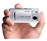
This project marks the fourth incarnation of the CamMan family of camera control chips. In this release we introduce a special PIC microcontroller that is used to interface a Sony digital camera to a standard model airplane radio control (R/C) receiver. The PIC has exciting new features that are not found in the earlier CamMan releases. As with the other CamMan projects, a microcontroller is used to connect the R/C receiver to the digital camera. The camera is the Sony Cybershot DSC-U20. It weighs only 4.1 ounces and has a 2.1 megapixel CCD sensor. With a 128 Meg memory stick it can shoot over 250 high resolution JPEG photos. The DSC-U20 has been discussed in detail on the eZone aerial photography forum. Note: The new Sony DSC-U30 is the same as the DSC-U20, so these instructions can be used on either camera model. Here are the main features of the CamMan-Sony Microcontroller:
The basic modifications center around a simple circuit that uses a microcontroller to decode the R/C "servo" signal, as well as manage the camera's shutter and exposure controls. Only four parts are needed; an 8-Pin IC, socket, capacitor, and resistor. But as simple as it all sounds, this isn't a project for the average electronic tech. Advanced soldering skills are needed due to the fine pitched soldering that is required. Do NOT attempt this project unless you have Surface Mount PCB rework experience and SMT soldering tools.
PIC Chip: Tiny But PowerfulCamMan is based on a tiny 8-Pin chip. It is a MicroChip Technologies PIC12C508 type microcontroller that uses custom firmware that you can download for personal use at no-charge. Even though a microcontroller is used, cost is very low. You can build the CamMan circuit for under $10. Total parts count is minimal and the assembled circuit weighs just a few grams. Project Update: You can also use the easier to find PIC12F508 or PIC12F509 instead.
The digital inputs are level sensitive and are said to be logic High when the voltage is > 2.0VDC and logic Low when they are less than 0.5V. Typical designs will use the VCC voltage (pin 1) for a logic highs and GND voltage (pin 8) for lows. The output sink current is 20mA (plenty for our application). Let's take a quick tour of the various signals on the PIC chip:
The PIC is not a "Flash"
part, so you will need a traditional
PIC chip programmer to "burn"
the hex file's object code into the microcontroller. Be sure to select the
programmer's configuration fuse settings as follows:
The PIC's Hex file is designed to automatically instruct the programming hardware to chose these values. However, it is always a good idea to check them for accuracy. By the way, after you program the PIC your programmer will report a failure if you attempt to verify the PIC again. Do not be alarmed -- everything is OK. Just ignore the "failure." Whatever you do, do NOT program the chip twice!
If you have trouble
burning the PIC, then please check your programmer. Whatever the fault, it
is not a RC-CAM hex file issue. The most common problem is that the
user has forgotten to burn the PIC's four configuration fuses, as mentioned
above. More programming information can be found starting
here.
It's All in the DetailsUnlike most of the other RC-Cam projects, I'm not going to offer detailed instructions on the CamMan-Sony modifications. Instead, I will summarize what I did and let you decide how you will build yours. If the project is not clear to you then that is an indication that you should not attempt it. I am very serious when I say that working on the Sony camera, with its flex circuit SMT construction, is a huge challenge. Even to the pros.
Total weight is about 6 grams. Please see the photo. The camera has six screws that you must remove. Two of the screws are in the battery chamber (remove the two AAA cells before starting the modifications). Once the screws are out you need to carefully spread the case apart, starting at the lanyard end. Gently pull it apart (by hand) as if it were a clam shell. The end closest to the lens is retained by an internal tongue so it will not release until the case halves are substantially pulled apart on the opposite side. Whatever you do, do NOT force anything and do not pry with a tool.
At this point you will have a pile of expensive pieces that looks like the photo on the right.
Solder the wires to the PIC as follows:
I needed a hole for the new cable. Instead of notching the camera case I removed the lanyard trim piece from the back metal cover. It is held by adhesive tape and will come off with a heat gun and some gentle prying. Be careful or you will dent the thin metal case.
All you have to do now is put the case back together. The connector will exit out the large hole where the lanyard trim was removed. You are done!
Set Up and Operation:I will assume that you will be sharing your throttle channel with CamMan. Using a servo "Y" adapter cable, connect the camera to the R/C receiver's throttle channel and to the servo or ESC (electronic speed control). Turn on the R/C transmitter and apply receiver power. Turn on the camera. First you must "Arm" the system. Move the throttle stick to full low stick then give it full up stick (do not cheat -- use FULL deflection on both extremes). CamMan is now armed and ready for flight. The arming procedure needs to be performed each time you turn on the camera or anytime the R/C transmitter or receiver has been off for more than five seconds. If the latter occurs, you will hear a three beep alert when the R/C signal is restored and the camera is ready for arming. When you reduce throttle to below 1/4 stick the camera will snap a picture. To take the next photo you must go to 1/2 stick or above, then back down again to below 1/4 stick. Practice a bit and you will quickly see how it works. If you listen carefully, you will hear the camera beep as each photo is stored. By the way, whenever the R/C signal is present, CamMan will disable the camera's automatic shut off. In other words, you do not need to take a photo every couple of minutes to keep the camera alive. However, if you turn off the R/C receiver, the camera will be allowed to go to sleep (may take up to three minutes to do so). If the camera does not take photos then you may have a wiring problem, your stick's trim lever is too offset, or an insufficient ATV mix setting in your R/C transmitter. First you should check your wiring. If it looks good, and the stick's trim lever is centered, then you will need to increase your ATV mix settings (if available) so that they are at 100% or higher. If you are using another channel besides throttle, be sure that its Dual Rates mix is disabled. If you are using a spare R/C channel (the gear channel works well) then the operation is nearly the same. To perform the initial system arming just flick the channel's toggle switch (or stick) down then up. From then on you have switch controlled access to shooting photos. Just flip it down/up for each photo. If the switch operation is backwards then either use your transmitter's channel reversing feature or simply reverse your arming and firing switch/stick direction.
Camera Creature Features:There are two new features on the CamMan-Sony. This version introduces Auto-Sequence and Stand-Alone modes. AUTO-SEQUENCE: When PIC pin-7 is tied to ground (pin-8) the camera enters Auto-Sequence mode. This allows for photos to be taken at three second intervals anytime the R/C channel is activated. After arming, just flip the switch on the R/C transmitter and fly around as the camera captures still frames for you. Flip the channel off to stop the photo session. You can also take single photos by quickly toggling the switch. This mode is not suitable for throttle sharing. STAND-ALONE: When PIC pin-6 in tied to ground (pin-8) the camera enters Stand-Alone mode. This allows for completely automated operation and eliminates the need for an R/C system. The camera will enter a thirty second delay whenever it is turned on. It will alert you with slow beeps which become faster when less than ten seconds remain. At the end of the delay, the beeping stops and the camera will take photos every five seconds. If Pin 7 is grounded, the photo timing is reduced to three seconds. The R/C channel will have no affect on the camera when this mode is used.
Design Documents:The technical details are available as file downloads. There is no charge for the firmware hex file when used in a personal hobby project. Commercial users and resellers must obtain written approval before use (license permission). Please be aware that the information is copyright protected, so you are not authorized to republish it, distribute it, or sell it, in any form. If you wish to share it, please do so only by providing a link to the RC-CAM site. You are granted permission to post links to the web site's main page (http://www.rc-cam.com/). Please respect this simple request.
The Small Print:
All information is provided as-is. I do not offer any warranty on its suitability. That means that if you build and use this device, you will do so at your own risk. If you find software bugs then please report them to me. I can only make corrections if I can replicate the bugs, so please give me enough details to allow me to witness the trouble.
FeedBack:I would enjoy hearing from anyone that uses the CamMan system. Please send me an email if you build it.
|
||||||||||||||||||||||||||||||||||||||||||||||||||||||||||||||||||||||||||||||||||||||||||||||||||||||||||||||||||||||||||||||||||||||||||
 There
are eight pins on the CamMan PIC chip. They exist as one of three kinds of
signals: Power, Digital Input, or Digital Output.
There
are eight pins on the CamMan PIC chip. They exist as one of three kinds of
signals: Power, Digital Input, or Digital Output.
 First I built a cable that has a servo plug on one end and a
4-pin header connector on the other. Sitting in the middle is the PIC, resistor
and cap, which are mounted on a 8-pin DIP machine pin socket. The PIC circuit
is protected in heatshrink tubing.
First I built a cable that has a servo plug on one end and a
4-pin header connector on the other. Sitting in the middle is the PIC, resistor
and cap, which are mounted on a 8-pin DIP machine pin socket. The PIC circuit
is protected in heatshrink tubing.
 Now that
the case is off you need to unplug the rear cover's ribbon cable from camera
body. Then remove the hidden screw that holds the top shutter switch assembly
in place. Once it is loose, unscrew the two screws that hold the trim to
the shutter switch's flex PCB.
Now that
the case is off you need to unplug the rear cover's ribbon cable from camera
body. Then remove the hidden screw that holds the top shutter switch assembly
in place. Once it is loose, unscrew the two screws that hold the trim to
the shutter switch's flex PCB.

 The
four wires are routed over to the battery end of the camera and terminated
in a 4-pin connector. Once the shutter switch trim panel is reinstalled (three
screws) you will have something that looks like the photo on the left.
The
four wires are routed over to the battery end of the camera and terminated
in a 4-pin connector. Once the shutter switch trim panel is reinstalled (three
screws) you will have something that looks like the photo on the left.