 |
||
|
||||||
Author commentary: Although the RC-CAM3 system is no longer used, you will certainly learn a lot by reading the details to building it. Like many good things, its useful life has come to an end and it has been replaced by the latest project called RC-CAM4. But for historical benefit, the original RC-CAM3 project is listed below. Enjoy!
 |
If you haven't
read about my RC-CAM1 or
RC-CAM2 prototypes then please click the links
at the top of this page. Otherwise, lets get into the details on how you
can build your own miniature video system for about $200. The project moves
quickly, so we will soon have it mounted on a radio controlled model
helicopter.
The improved wireless camera system is called RC-CAM3. If you built the RC-CAM2 system and would like to upgrade to this better design, then do not despair. Fortunately, you can re-use most of the electronics from the other system. But you will need to restore your XCam video transmitter to its original factory state. Yes, oddly enough, we must move backwards before advancing to the future. So, if you have built the other system then just remove the modifications that were made to the video sender/transmitter and reinstall the circuit board in the original plastic case. I will not specifically address the resurrection of your XCam video transmitter, since most folks joining our project will be using brand new parts. |
RC-CAM3 can be built using the discontinued "XCam" or the newer "XCam Anywhere" camera systems that are sold by x10.com . You should also be able use their "DVD Anywhere 2000," which is a camera-less version of the XCam. This equipment appears to be very similar to the Radio Shack #15-1971 Room-to-Room A/V Link.
There is a lower cost
wireless camera called XCam2, but this system is a one-piece design
(camera and transmitter are integrated). Sometime later this year (Sept 2001)
I will post the details on to how to hack this camera. In the meantime, you
are on your own if you use it or any other brand of wireless Audio/Video
transmitter. By the way, the RC-CAM
user-to-user forum
has lots of information on nifty XCam2 hacks.

Although you may be using one of the other A/V video products that was mentioned, I will specifically address the modifications that are needed to use the XCam Anywhere system. The vendor that sells this item offers a full description of it at http://www.x10.com/products/x10_vk34a.htm.
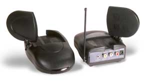
I will just refer to the video system as XCam. It currently sells for $88, which is a very reasonable price for a color camera, 2.4 GHz transmitter and receiver. You even get some nice cables too. The photo on the right shows the major elements of the stock system. To see more, just click the photo. In case you haven't noticed, the original XCam, the new XCam Anywhere, and the DVD Anywhere 2000, all use the same video transmitter and receiver units.
The XCam transmits on 2.4 GHz and does NOT require a ham radio license to operate. As you may recall, this was an issue with my original RC-CAM1 which operated on the 434 MHz ATV HAM band. Line-of-site range is about 300 feet. A better receiver antenna would easily double the range, but I have not had the need to design one (my video recording is mostly while hovering and close range forward flight).
But, we will not use the color camera that is included with the XCam, since it does not work well in our application. This entry level camera is based on a consumer quality CMOS video chip. It was designed for fixed installations, so the auto-iris is easily confused when the background intensity changes. Unfortunately, as we fly our helicopter around this issue becomes a nuisance and translates into washed out and/or dark pictures.
 The RC-CAM3 video improvements
are due to the use of a
Panasonic
GP-CX161-53P CCD color camera. This is a tiny but very high quality chip
camera and it is available for about $100. Its on-board microprocessor ensures
that we get the optimum video quality, even with the rapid light intensity
changes that occur while we fly our model aircraft. It weighs barely eight
grams, making it a perfect match for our application.
The RC-CAM3 video improvements
are due to the use of a
Panasonic
GP-CX161-53P CCD color camera. This is a tiny but very high quality chip
camera and it is available for about $100. Its on-board microprocessor ensures
that we get the optimum video quality, even with the rapid light intensity
changes that occur while we fly our model aircraft. It weighs barely eight
grams, making it a perfect match for our application.
But, the higher performance comes with a price. It is a bare board camera and so it does not have an enclosure -- just a nice glass lens mounted on a small 1" square circuit board. Also, it is based on a CCD imaging array, so the current draw is quite high -- about four times greater than the earlier camera. But, none of this is a major issue.
Ok, where are we going with all of this? Let's see... we need lightweight airborne electronics, simple battery operation, and an small omni-directional antenna. But wait, the XCam system is kind of bulky, is powered by household current, and has a big crummy antenna system. Time to put on the tool belt!
Like RC-CAM2, this project involves modifications to the stock XCam transmitter. But, the alterations that we will make are minor compared to those made on the RC-CAM2 system.
So, let me impress upon you that you must check your XCam system to see if it works before you attempt my modifications. This is your chance to see if your new XCam system works correctly and to your satisfaction. If not, return it now.
We do NOT need to alter the transmitter's circuit board, but we still need to open up the case. So, grab the transmitter unit, labeled "VT30A," and remove the four (4) bottom case screws. You may wish to peel off the rear label too (heat it with a hair dryer first).
Before I continue lets get one thing perfectly straight. By taking the product apart you have no moral or legal right to return the unit to the vendor. If you damage it, then you lose. If becoming the not-so-proud owner of a dead camera system freaks you out then by all means put away the screwdriver before you dork the unit up!
 As I mentioned, the Video
Sender transmitter is marked VT30A. It is the unit with the vertical
whip antenna on the side. Do NOT take apart the identical twin receiver
identified as the VR30A.
As I mentioned, the Video
Sender transmitter is marked VT30A. It is the unit with the vertical
whip antenna on the side. Do NOT take apart the identical twin receiver
identified as the VR30A.
Now with the case apart you can look inside the video transmitter. You should be able to quickly identify the coax cable connecting the RF section's metal can with the Mickey Mouse Ear style polar antenna. Also note the wire connecting to the vertical whip antenna.
If you do not feel comfortable poking around the guts of the transmitter then STOP, re-install the cover, and don't look back. Otherwise, let's march forward.
Ok, enough with our initial transmitter geography. It's time to remove the undesirable Mickey Mouse Ear (MME) antenna and the dummy vertical whip antenna. Here is what I did:
|
 |
The XCam video transmitter requires at least 9.6 VDC. However, the radio control system in my model helicopter is powered by a 4.8 VDC battery pack, which thankfully is compatible with the Panasonic camera. But shucks, the camera draws too much current to be safely shared with the model's R/C gear.
But this situation is not a problem. I could have used a second 4.8 VDC NiCd battery pack for the camera and a 9.6 VDC NiCd for the XCam transmitter, but I wanted a more elegant solution. The thought of three battery packs seemed excessive to me.
Using two battery packs is probably easier to deal with than using three. This will certainly simplify the installation at the expense of a little up-front work. But you can skip my high tech solution and simply use three battery packs. One for the R/C gear, a separate 4.8 VDC @ 600mAH battery to operate the Panasonic camera, and a 9.6 VDC @ 300 mAH battery to power the XCam transmitter. By the way, all of these battery voltages are compatible with a standard R/C system's battery charger.
The custom power supply circuitry I devised will allow me to run the camera AND video transmitter from a spare 4.8 VDC/600 mAH NiCd battery pack.
| CAUTION: Do NOT share your R/C gear's battery with the camera system. The combined current draw is substantial and your model's R/C receiver and servos will be affected. Can you spell C-R-A-S-H? |
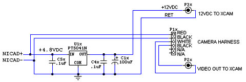
Our battery reduction magic is obtained from a tiny DC-DC power converter. The idea of using a DC-DC power module began with RC-CAM2. In our new application we will step-up the 4.8V battery to 12 volts and plug it directly into the power entry jack on the Video Sender transmitter. If you wish to use the three battery solution, just directly plug a 9.6 VDC battery into the transmitter.
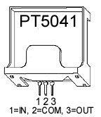
But I will assume that you are interested in using my battery reduction circuit. The trick is performed by a PT5041N, a special voltage regulator IC offered by Texas Instruments (Power Trends division). It is nearly ready to use -- just three low cost filter capacitors are needed on the output (see the data sheet). To use this little jewel you just apply roughly 5VDC in and you instantly get 12 VDC out. Gosh, this is getting too easy!
The electronic components can be obtained from www.digikey.com, www.mouser.com and www.supercircuits.com.
Of course you can use your local supplier if you know how to substitute the parts. But PLEASE don't email me asking for my opinion of your sub'd part. If in doubt please go to these sources. If mail order is not convenient then by all means use your favorite source.
Let me remind you that I do not work for, nor represent, ANY supplier of the parts used in RC-CAM. Any reference to a vendor is for your convenience and I do not endorse or profit from any purchase that you make.
Qty |
Description |
Reference |
Source |
1 |
Panasonic Color Camera, GP-CX161-53P, 53 degree optics |
N/A |
SuperCircuits PC-87XS |
1 |
Panasonic Color Camera Cable | P1x |
Digi-Key P9507-ND |
1 |
5V to 12V DC-DC Convertor | U1x |
Digi-Key PT5041N-ND |
1 |
100uF 16V Electro Cap, low ESR | C1x |
Digi-Key P11198-ND |
2 |
1uF 50V Ceramic Cap | C4x, C5x |
Mouser 80-C330C105K5R |
1 |
RCA Phono Plug | P2x |
Mouser 174-4357 |
1 |
DC Power Plug, 2.5mm x 5.5mm | N/A |
Digi-Key CP-004B-ND |
1 |
DC Power Plug, 4.7mm x 1.7mm | P3x |
Mouser 171-3220 |
1 |
Pactec Enclosure #K-JM22 2.4W x 2.3L x 1.0H |
N/A |
Mouser 616-69313 |
Qty |
Description |
Reference |
Source |
2 |
10K ohm 1/8W Resistor | R1x, R3x |
Mouser 299-10K |
1 |
100K ohm 1/8W Resistor | R2x |
Mouser 299-100K |
1 |
1uF 25V Electro Cap | C2x |
Mouser 140-XRL25V1.0 |
1 |
.1uF 50V Mono Cap | C3x |
Digi-Key P4923 or Mouser 80-C322C104K5R |
1 |
LM358 OPAMP IC | U2Ax |
Mouser 511-LM358N |
1 |
8 Pin DIP Socket | U2x Skt |
Mouser 535-08-3518-10 |
1 |
Electret Microphone | MICx |
Mouser 25LM044 |
2 |
RCA Phono Plug | P4x, P5x |
Mouser 174-4357 |
We will build the circuit elements in stages and test each one. The two circuits are the DC-DC Power Supply and the Microphone Preamp. Here is what we will be building. Are you up to it?


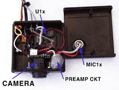
(1) Plastic Enclosure Layout
A plastic enclosure will house the color camera board, the DC-DC convertor, and the optional microphone preamp. The Pactec K-JM22 enclosure is the perfect size, but you can freely choose any other plastic box that you wish.
The photo on the right shows the front holes that I drilled to mount the Panasonic Camera board. The larger hole is slightly bigger than the camera lense and the two smaller ones are drilled to accept 2-56 machine screws. Just use the Panasonic camera to mark their locations.
(2) Main
Power Supply and Cable Assembly
The DC-DC chip, labeled U1x in the schematic, is functional right out of the box, but we need to add a filter capacitor and the connectors. We also need to add some power connectors for the XCam transmitter (12V) and Panasonic camera (4.8V).
 |
 |
I'll try not to go into the details of how to solder the parts together since each electronic tech has his/her favorite method. In my unit everything is mounted "dead-bug" style and fits snugly in the PacTec box. The special Panasonic camera harness (P1x) is a must have item. Please recognize that your finished work will go into a very harsh environment (severe vibration and G-forces) so build it as such.
 I did not install a power
switch. Rather, I installed a female servo connector on the circuit's NICAD
input so that I could unplug the battery when it is not in use. Pay attention
to the polarity or I suggest you look for some good fire insurance.
I did not install a power
switch. Rather, I installed a female servo connector on the circuit's NICAD
input so that I could unplug the battery when it is not in use. Pay attention
to the polarity or I suggest you look for some good fire insurance.
Before applying power to your newly completed circuit please unplug the camera harness and XCam power cable. If you made a wiring mistake these expensive parts WILL be destroyed.
Give your finished wiring a thorough visual inspection. When satisfied that you made no errors, take your ohmmeter and verify that you do not have a short across the "NICAD" input. The resistance should be over 2K ohms. If not, fix your mistake now or prepare a bucket of water.
It's time to get serious. If you have a regulated bench supply then set it for +4.8 VDC (5.0 is fine too). If possible, limit its current to about 500mA. Otherwise you will need to use a 4.8VDC 600mAH NiCd battery pack. But hold on, don't apply power just yet.
Here are my recommended
start-up tests:
(3) Microphone
Preamp
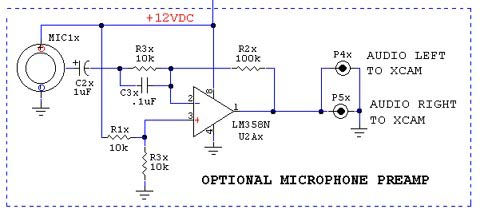
I wanted to record the audio while flying, so I added a little electret mic and preamp circuit. You may not care about audio (but it adds another dimension to the recorded flying experience) so just ignore this circuitry if you wish to omit the mic feature.

I built the preamp
on the bottom of an 8 pin DIP machine pin socket. Keep the component leads
short and follow the schematic.
After mounting all
the discrete parts to the bottom of the socket, connect the preamp to the
three mic leads (Power, Signal, Gnd). Using about five inches of stranded
wire, connect the preamp to +12V and Gnd of the regulator circuit. Solder
RCA plugs to the output of the preamp. Use enough cable to reach the left
and right audio input jacks on the XCam transmitter.
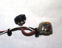
Cover the finished preamp circuit with heatshrink tubing or electrical tape. The microphone element is mounted in a big rubber grommet, which is glued to the top half of the Pactec enclosure. Drill a 1/8" hole in the enclosure near the center of the mic.
(4)
Flexible Rubber Ducky Antenna
The old RC-CAM2 used a full wave vertical whip antenna. Our new system will use one that is about half the size. Hey, wait a minute -- won't a shorter antenna reduce the system's range? No, it will actually improve it.
You see, the RF wavelength of our 2.4 GHz system is about 4.7 inches. An ideal antenna of similar length would provide the best reception. But, the coax cable connected antenna is optimized for a 50 ohm load, which is the typical impedance of a 1/4 or 1/2 wave antenna. Using good impedance matching increases the efficiency of the overall antenna circuit.
I settled on a "rubber ducky" style half-wave dipole antenna. It is not very efficient (RF wise), but it is easy to build and is rugged too. It is not a traditional dipole since I rotated the elements 90° and layed the grounded element against the coax cable (see photos). It is made by carefully trimming some insulation off the XCam's coax, adding two short wires, then covering everything with heatshrink.
 |
Start by cutting two pieces of 18 AWG solid wire to EXACTLY 30 mm (1.18 inches) long. These will be the antenna's quarter-wave dipole elements. They are shown in the sample photo, on the left, as the orange colored wires. Accuracy counts on this exercise, so measure VERY carefully. |
| Now, trim the
end of the XCam's coax cable so that a tiny length of the shield and center
conductor is exposed. These will be soldered to the 30mm dipole wires that
you just cut. The inset at the right shows the intricate soldering that is
required. Make sure that the center conductor is not shorted to the shield
when you are done (use your ohmmeter). Clean off the flux too!
|
 |
For a better antenna you can substitute the shield connected element with a piece of brass or copper tubing. It will slide OVER the shield (protected by the outside coax insulation) and then be soldered to the shield as before. I found some brass tubing at the hobby store that was a perfectly snug fit over the coax. A similar method uses just the coax shielding. It can be folded over itself to accomplish the task. But, the XCam coax length is too short for this nifty trick.
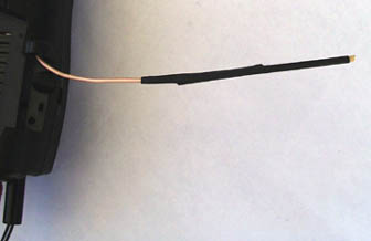 |
One of the elements is now sticking out and is unsupported. This is a rather fragile configuration, don't you think? Now for the "rubber ducky" part. Cut a piece of heat shrink tubing to about 7 cm long. Slip the heat shrink over the two exposed elements and apply heat. Repeat this with two or more heatshrink applications. You now have a durable flexible antenna. |
The antenna must hang down vertically during flight. This is the best orientation for good reception. All I did was to bend the coax a little to help the antenna tip drop down and the weight of the heatshrink does the rest. The best antenna mounting location is below your model helicopter. In a moment you will see what I did.
(5) System Checkout
 The photo on the right shows
you what my custom airborne equipment looked like at this point . With luck,
yours will look similar.
The photo on the right shows
you what my custom airborne equipment looked like at this point . With luck,
yours will look similar.
To check the camera and microphone you will need to install the XCam receiver on your TV or VCR and apply power to everything.
Verify that you have video and audio. If you run into trouble then check that the XCam transmitter and receiver are still set to the same channel (A-B-C-D) and that their On/Off switches are "on."
Turn on your model's R/C transmitter and move twenty feet from the XCam equipment. If you find video interference then change the XCam transmitter and receiver to a different A-B-C-D channel. My radio caused lots of snow on two of the settings.
Perform a video system range test. You should get up to 100 feet inside the house and about 300 feet while outdoors (line of site). Verify that the mic works too.
We need to make a battery cable for the VR30A XCam receiver since it normally uses a 12VDC AC wall adapter. I know you don't want to drag 115VAC mains power to the flying field to operate the ground equipment.
You can use your 12V GelCell field (starter) battery to operate the XCam receiver. All you need is a 5.5mm x 2.5mm power plug and some cable.
Use a six foot length of 22AWG color coded two conductor cable and solder the red lead to the center post and the black to the shield lug of the power plug. Solder some alligator clips to the bare ends or use banana plugs if you use a power panel. Color code everything or invest in a fire extinguisher!
Whenever your XCam receiver needs power just clip it on to your 12VDC field battery. I recommend that you find a way to avoid reverse voltage issues since the XCam receiver will go up in smoke if you make a connection mistake at the field (oh, that will never happen you say?).
All that remains is to mount the camera system on your model heli. I'll leave the exact details to this task up to you, since each aircraft will be different. Just use your creative talents to install the video gear. But to help you out, I will summarize what I did.
On my Concept 30 model helicopter I fit everything between the landing skids near the model's center of gravity. After playing around with different arrangements, I decided to flip the video transmitter over (upside down) and mount the camera on top of it.
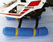 This
created a compact package, but my helicopter did not have enough height under
the skids to accommodate everything. This was easily fixed by installing
some 3" diameter pool noodles, those crazy colorful foam tubes that
kids use to float in the water. I just cut the foam noodles about 4" longer
than my skids, made a shallow lateral cut, just like a hot dog bun, and then
slipped each noodle onto a landing skid. Several rubber bands and plastic
tape hold them securely. I like these fat skids so much that I leave them
on even when the camera gear is not being used.
This
created a compact package, but my helicopter did not have enough height under
the skids to accommodate everything. This was easily fixed by installing
some 3" diameter pool noodles, those crazy colorful foam tubes that
kids use to float in the water. I just cut the foam noodles about 4" longer
than my skids, made a shallow lateral cut, just like a hot dog bun, and then
slipped each noodle onto a landing skid. Several rubber bands and plastic
tape hold them securely. I like these fat skids so much that I leave them
on even when the camera gear is not being used.
I wanted the video transmitter, color camera, and NiCd battery pack to be a one-piece deal. You know, something that would easily come off in a minute or less. It had to be durable and offer some protection against vibration. Since very little can be done to provide real crash protection, I did not burden my design with such amenities (airbags and seatbelts, anyone?).
I fabricated a simple platform design. I merely took some flexible 3/32" sheet plastic (you could use hobby plywood) and I cut a 11.5" x 2" piece to act as a skid mounting brace. The length was based on the width of my noodle equipped landing gear, so your dimensions could be different.
 To keep
fuel and oil off the transmitter's connectors, I decided to face them towards
the front of the model (furthest point away from the engine). Using four
4-40 machine screws, the plastic brace was attached across the center of
the Video Transmitter. Since the transmitter is upside down, its flat surface
lays nicely against it. At the ends of the brace I punched some holes and
looped #64 model airplane rubber bands through them. They will be used to
strap the equipment to the helicopter.
To keep
fuel and oil off the transmitter's connectors, I decided to face them towards
the front of the model (furthest point away from the engine). Using four
4-40 machine screws, the plastic brace was attached across the center of
the Video Transmitter. Since the transmitter is upside down, its flat surface
lays nicely against it. At the ends of the brace I punched some holes and
looped #64 model airplane rubber bands through them. They will be used to
strap the equipment to the helicopter.
I then cut a 6" square piece of clear lexan to use as a splash shield. It is mounted on top of the brace and its purpose is to prevent fuel from getting into the electronics. I highly recommend this feature.
Using servo mounting tape, I installed the camera assembly on top of the splash shield. For shock and vibration protection, there is a piece of 1/2" thick rubber foam between the shield and camera assembly.
The battery pack is mounted on the splash shield behind the camera (I also put a small splash shield over it). Again, double-sided servo mounting tape holds everything together. Although this may sound like a fragile arrangement, it is very strong and works great. Total weight (with batteries) is 14 ounces.
To install my platform based video system I just slide it on top of the foam noodles, attach my rubber band straps together, and go fly. Installation is about thirty seconds. Whatever you build, please use common sense or you may drop "camera bombs" while flying.
I find that the video antenna works best if it is allowed to hang free under the helicopter. Mine drops below the model after take-off (almost vertical), which provides good range for me. If the antenna is near the model's body the range will decrease. I get very reliable reception to about 200 feet, which is perfect for making hover videos and close forward flight scenes.
Longer range will require a better antenna on the video receiver, but that part is up to you. Just in case you ask -- Yes, a high gain yagi or dish antenna design could increase your range to about 1,000 feet.
If at any time you find video interference then change the XCam transmitter and receiver to a different A-B-C-D channel. If anything appears strange DO NOT FLY until you resolve the trouble.
|
Hey, its time to fly. When you get to the flying field you should do a complete range check on your R/C system and the RC-CAM. Just connect the RC-CAM receiver to your camcorder, set it for the A/V input mode, and use its eyepiece monitor to see the transmitted video.
Quiet on the set. Lights, Camera, Action. Enjoy!
|
** USE THIS SITE'S INFORMATION AT YOUR OWN RISK! **
Model Helicopters are not toys and should be flown under the supervision of an experienced adult pilot. Our web space sponsors are not responsible for the content of this site and do not endorse radio controlled model helicopters or the use of video camera equipment on them. Our sponsors and/or the web site's authors are NOT responsible for any personal injury or property damage resulting from using the published information.
![]()
![]()
![]()
![]()
Legal Information
© 2000-2015 RC-CAM