|
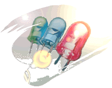 LED
Calculator LED
Calculator
Optimized
for R/C Applications
Are you
installing LED's on your R/C model? Tired of
trying to figure out the LED's resistor value? If so, then let this LED Calculator do all the work for you!
The "LED Roundup" section offers useful advice on choosing
the best LED's for your model.
|
Using LED's on R/C models
has become very popular. The can dress up a scale model and the latest
high-lumen LED's are so bright that they are perfect for night time
flying. The only trouble is that
most folks are a bit perplexed by the current limiting resistor. Every
LED needs one, but determining its resistance and wattage can be confusing. Not any longer -- this online calculator will turn that
chore into an easy matter.
This web page is based on work done by
Rob Arnold,
the creator of a general purpose LED calculator that I found on the web. Although I have added
many new features, at the core of the javascript code is basically
his talented work.
If you have
experimented with LED's then I suggest that you move on down to the
calculator and get on with using it. If LED's are still a bit of a
mystery to you, then please continue reading.
Basic LED Information
LED's are not at
all like a common "light bulb." They do not have a filament,
nor due they use any of the other traditional methods to produce light.
Instead, they are a cousin to common diodes (that is why they are called
Light Emitting Diodes) and are truly solid state. That means that if
they are not abused by excessive current, they will probably last longer
than any of us mortals.
LED's are
actually current operated devices rather than voltage
devices. That means that you can safely use any voltage that is higher
than the LED's forward voltage (more on that in a minute) as long
as you manage the current. That is the purpose of the resistor. So, to
use an LED you will need to install a current limiting resistor and then
apply a suitable DC voltage from a battery. In our R/C application, the expected
battery voltages range from about 3.6VDC to about 24VDC. LED's
are polarity sensitive, so you will need to observe how you connect the
battery. The LED's anode is always positive (+) and is usually
identified by a longer lead (there are exceptions). On LED's with a flat
spot around the lens base, the flat mark ALWAYS indicates the cathode
lead, which connects to the battery negative (--) terminal. By the way, the
resistor can go on either lead. At
one time nearly all LED's would work on voltages as low as about 2VDC.
However, with the introduction of new colors, the minimum operating
voltages, called the forward voltage (Vf), are now all over the
map (1.7 to 4.5 VDC). Unlike a light bulb, low voltages do not cause dim operation.
Instead, if the battery voltage is below Vf, no light will be produced.
Nada, Zip, Zero. It is important that you note the Vf rating of the LED
since this value will be needed when you attempt to use the
calculator. Guessing is not an ideal option.
In
most cases, you will be using an LED with a Vf of about 4 VDC for blue
and white and 2V for all other colors. However, the
actual value will come from the data sheet of the part you bought. You
can ignore the Reverse Voltage (Vr) specification since it is
only important if you use the LED on AC power sources.
Generally
speaking, the higher the current, the brighter the LED will be. The operating
current you choose will nearly always be about 20 to 30mA. Higher
currents are used on some LED's, sometimes as much as 50mA. But, please be aware that if
the chosen current is excessive then the part will sadly go to diode heaven. Also, high currents
will cause the LED to get too hot, which causes them to dim. My point
is, do not push the LED current unless you are sure you know what you
are doing.
How Do I Power My LED?
All R/C models have
onboard batteries that are great sources of power for running your
LED's. Usually there is a 4.8V or 6.0V rechargeable battery that powers
the R/C receiver and you can just share this voltage with your LED's.
And if you don't go crazy, the extra load on the pack is minimal.
Rather than
connecting directly to the battery, a preferred method is to have the LED's use a spare servo jack on
the receiver. If you do not have a spare output, then just use a
"Y" cable adapter and have the LED share an output with one of
the servos. Tapping
into the servo plug is easy. There are three wires; the center one is
positive and the outside brown or black wire is negative. The third wire
is not used by the LED. Using
the servo output on the R/C receiver is especially useful with electric
powered models. They often use 7.2V and higher battery voltages (which
is fine for LED use). But, if you connect to the receiver's servo
output, then your LED brightness will be consistent as the battery pack
is used in flight. This trick capitalizes on the Battery Eliminator
Circuit (BEC) that is in the motor's Electronic Speed Control (ESC). The
BEC output provides a regulated voltage of about 5V which your receiver
can share with your LED's. However, do not overload the BEC with
too many lamps or you may loose control of your model during flight. The
number of LED's you can connect will depend on the BEC's current rating,
cell count, number of servos, and LED current draw. Please do not ask me for advice
on how many LED's your ESC can handle -- I will not know.
 The drawing on the right shows how a pair of wingtip LED's are wired into a standard R/C servo connector. Because it only draws 40mA when used with a
5VDC source, this
simple circuit can be plugged into a spare receiver channel or Y-connector'd with an existing servo. The drawing on the right shows how a pair of wingtip LED's are wired into a standard R/C servo connector. Because it only draws 40mA when used with a
5VDC source, this
simple circuit can be plugged into a spare receiver channel or Y-connector'd with an existing servo.
The LED's are
polarity sensitive, per the "A" (anode) and "K"
(cathode) notations. The resistors go in series with each LED. You will soon see how to use the LED calculator to determine the
resistor values.
LED
Roundup
LED's come in hundreds of choices, so finding
those that are good performers for lighting up a model aircraft is a daunting task.
Nighttime R/C pilots are interested in good lamp brightness (high mcd) and a wide viewing
angle.
I ended up buying dozens
of LED's from Mouser, Digi-Key,
Super Bright
LEDs, and Electronic Goldmine. I checked them for brightness
and illumination spot size. I was surprised to find that many of the LED's
did not perform as well as expected, at least in the cases where the data
sheets hinted that I should have been more impressed.
My simple tests
consist of a projector screen and variable LED current source. On a
one-by-one basis, I observed each LED in a dark room.
I measured the spot size at a fixed distance and judged the brightness. Using currents
in the 20mA to 50mA range, I determined the most efficient value (good light
output at a reasonable current). At the end of my tests I assigned a
score to each LED using a 0 - 9 scale value (0=poor, 9=excellent).
The table below shows
the results from several LED's that I tested. Those not shown were
such poor choices that I won't bother to clutter the table with their data.
My overall Score is shown in the comments section in
the table below.
Legend:
Green =Best choice,
Orange = Fair choice,
Violet = Poor choice, Red = Don't use.
Part No. |
Source |
Color |
Typ mcd |
View Angle |
Size |
Typical mA |
Vf |
Score/Comment |
604-L7104VGC/H |
Mouser |
Green |
11000 |
34º |
3mm |
25mA |
3.7V |
9 / Wide spot, very high brightness. Recommended. |
RL5-W6030 |
Super
Bright LEDs
|
White |
6000 |
30º |
5mm |
25mA
|
3.2V |
8 / Wide spot, high brightness. Perfect
for Landing lights. |
RL5-A7032 |
Super
Bright LEDs
|
Aqua |
7000 |
32º |
5mm |
20mA
|
3.6V |
8 / Medium spot, high brightness. |
RL5-R8030 |
Super
Bright LEDs
|
Red |
8000 |
30º |
5mm |
20mA
|
2.2V |
8 / Medium spot, high brightness. |
604-L7104QBC/D |
Mouser |
Blue |
1500 |
25º |
3mm |
25mA |
3.5V |
7 / Wide spot, high brightness. Good for
wing tips. |
| 160-1512 |
Digi-Key |
Amber |
1800 |
60º |
7.6mm Sq |
45mA |
2.2V |
7 / Huge
Spot, medium brightness. |
G12702 |
Electronic Goldmine
|
Blue |
3000 |
25º |
5mm |
25mA
|
3.2V |
7 / Wide spot, high brightness.
Recommended. |
RL5-W10015 |
Super
Bright LEDs
|
White |
10000 |
15º |
5mm |
20mA
|
3.4V |
7 / Narrow spot, very high brightness.
Good for strobe use. |
604-L7114QWC/D |
Mouser |
White |
3200 |
20º |
5mm |
25mA |
3.5V |
7 / Medium spot, high brightness. Good for landing lights or strobe. |
RL5-G8045 |
Super
Bright LEDs
|
Green |
8000
|
45º |
5mm |
20mA |
3.5V |
6 / Very Wide spot, medium brightness. |
| 604-L7104QWC/D |
Mouser |
Blue |
2200 |
34º |
3mm |
20mA |
3.5V |
6 / Wide spot, medium brightness. |
G12703 |
Electronic Goldmine
|
White |
2500
|
15º |
5mm |
25mA |
3.5V |
6 / Narrow spot, medium brightness. Good strobe light. |
G12993 |
Electronic Goldmine
|
Yellow |
3000
|
15º |
5mm |
20mA |
2.2V |
5 / Medium spot, low-med brightness. |
| MV8305 |
Digi-Key |
Yellow |
2000 |
20º |
5mm |
20mA |
2.0V |
5 / Narrow
spot, med-high brightness. |
604-L53SRCE |
Mouser |
Red |
3500 |
30º |
5mm |
20mA |
1.9V |
5 / Narrow spot, medium brightness. |
604-L7104SRC/J |
Mouser |
Red |
2300 |
34º |
3mm |
20mA |
1.9V |
4 / Medium spot, low-med brightness. |
| CMD333UWC |
Digi-Key |
White |
2000 |
20º |
5mm |
20mA |
3.8V |
4 / Medium
spot, medium brightness. |
604-L7113SYC |
Mouser |
Yellow |
1200 |
20º |
5mm |
20mA |
2.0V |
4 / Narrow spot, medium brightness. |
G12769 |
Electronic Goldmine
|
Green |
3000 |
15º |
5mm |
20mA |
3.5V |
4 / Narrow spot, medium brightness. |
G12766 |
Electronic Goldmine
|
Org-Red
|
4000 |
25º |
5mm |
20mA |
2.1V |
4 / Medium spot, low-med brightness. |
604-L934SRCF |
Mouser |
Red |
1200 |
50º |
3mm |
20mA |
1.9V |
3 / Medium spot, low brightness. Skip this one. |
604-L813SRCE |
Mouser |
Red |
3000 |
40º |
10mm |
20mA |
1.9V |
3 / Huge lamp. Smaller than expected Spot, medium brightness. Skip
this one. |
| 404-1114 |
Digi-Key |
Yellow |
425 |
70º |
3mm |
20mA |
2.2V |
2 / Wide
spot, low brightness. Skip this one. |
G12922 |
Electronic Goldmine
|
Light Green |
? |
? |
5mm |
20mA
|
2.2V |
1 / Very Dim. Skip this one. |
604-L934SGC |
Mouser |
Green |
300 |
50º |
3mm |
20mA |
2.2V |
1 / Narrow spot, low brightness. Skip this one. |
Using
the Calculator
To use the
calculator all you need to do is enter three simple parameters:
- Enter the
Battery Voltage.
If you are using your ESC's BEC output, then enter 5VDC.
- Enter the LED's
forward voltage (Vf) specification. Get this from the LED's data
sheet. If you are using two LED's in a series connected
string, then add all the Vf's together and enter it as one value.
Total Vf's must be less than your source voltage.
- Enter the
desired LED current you wish to use (20mA works well for most
R/C applications). Do not
exceed the maximum current rating shown on the data sheet (reduce
the value shown by at least 20%).
Once you
supply this basic information, just click the button and the calculator will do several useful
things:
- It tells you
what the calculated current limiting resistor value is.
- It finds the
standard resistor value from the common 5% tolerance offerings.
- It
suggests the
standard minimum resistor wattage you should use.
- It shows you
the resistor's color code.
- It
determines
dissipated power of the LED and resistor. You will be warned if it
appears unsafe.
- It looks up
the Mouser and Digi-Key part numbers for
you. Of course these parts are nothing special, so get 'em from
Radio Shack if you wish.
Geez, does it
get any better than this?
Step 1: Enter your requirements
Beware of the Fine Print:
All information is
provided as-is. I do not offer any warranty on its suitability. That means
that if you use this calculator, you will do so at your own (and the
LED's) risk. If you find problems then please report them to me. |
Feedback:
If you have
technical questions or comments about this project then please post it
on the rc-cam
project forum.
© 2002-2016 RC-CAM, all rights
reserved. |
|